How Ro Read a Car Wiring Diagram
A machine wiring diagram tin look intimidating, but once you understand a few basics yous'll see they're actually very unproblematic.
A car wiring diagram is a map. To read it, identify the excursion in question and starting at its power source, follow it to the footing. Use the legend to empathise what each symbol on the circuit means.
I'm an motorcar technician for over twenty years, I've always loved the electrical side of auto repair. Later on reading this post you'll understand how to read a bones wiring diagram, which as you know is key to finding electrical problems rapidly.

Understanding A Basic Circuit
Here I'll explain the basic principle behind a circuit. This stuff is like shooting fish in a barrel and if you're already familiar, yous tin can skip it.
A wiring circuit is so-called considering the wiring must make a complete circle in order for voltage to catamenia. A pause or brake in the circle will cause an intermittent or permeant fault.

Power leaves the positive (Red plus sign) side of the car bombardment through the power cablevision and is e'er actively looking for the shortest possible return path to the negative (minus sign on the bombardment casing) side of the car battery.
The path back to the negative side of the battery later the load is known as the ground path. The load is any the consumer is, in the case of the above diagram it's the light.
Bones wiring circuit diagram
Obviously, there'll be more circuitous-looking circuits, which volition have relays and control units, just remember, they all operate nether the aforementioned basic idea.
Power leaves the battery positive and looks for the shortest path to the ground side of the circuit.
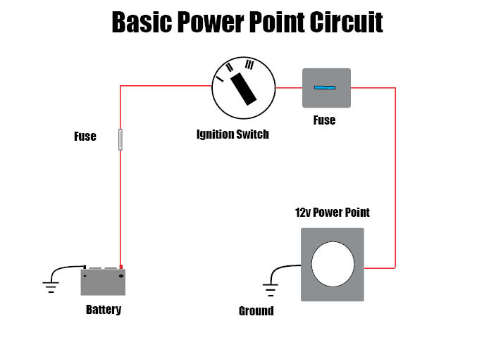
A typical basic circuit consists of 5 important parts:
- Power supply (Positive from bombardment)
- Fuse (Protects the excursion from overload)
- Switch (Manual or controlled)
- Load (Light seedling, motor etc.)
- Ground (Render path to negative side battery)
What's Power?
Power is battery voltage and in whatsoever circuit, the path to the load from battery positive may be described as the power side of the circuit.
What's Ground?
As you know, voltage loves to travel through any metal, and not just the metal inside wires. A ground is therefore any metallic part of the chassis or engine that'due south connected to battery negative.

The return path after the load is known equally the ground side of a circuit. And typically isn't drawn on a diagram equally a wire going dorsum to the negative side of the battery, instead a ground symbol is used.

What's A Relay?

Relays haven't inverse very much over the years, they're in old cars and new ones, a good idea never gets one-time.
The office of a relay is to control a high amp circuit similar a starter motor or headlights using a low amp switch excursion.
Running high amps through a small switch would cause the switch to burn out and neglect, possibly starting a fire.
Relays are common in circuits and as well housed within command units. When they're integral to the control unit, the diagram will ofttimes refer to it, but information technology won't be a serviceable relay.
Traditionally, relay terminals were numbered using double digits, but the latest versions utilize single digits, I've marked both on the diagram below.
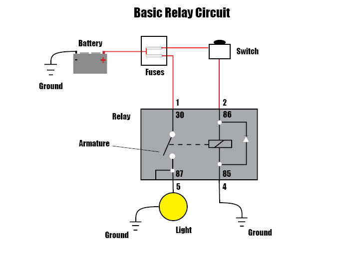
How's it work?
A relay is an electromagnetic switch, information technology has two carve up circuits, a Command circuit, and a Load excursion. A switch is either manually operated or a control unit of measurement sends power through the 2/86 last which passes to the ground through terminal 4/85.
This causes the curlicue of the relay to get magnetic, which pulls the movable armature within the relay, closed. When closed (open in the above diagram), it allows ability travel from the battery to the light. (Through the 30 and 87 pins)
If you need help understanding DVOM aka multimeter, cheque out the how-to-apply multimeter Kindle books on the Amazon link below.
Amazon How To Use Multimeter

When the switch is turned off, (battery asunder) the whorl is no longer magnetic and the spring-loaded movable armature returns to open up (default position).
Pro tip: When fault-finding circuits, a quality DVOM is mission-critical. Cheap voltmeters are OK for finding power and grounds, but mod vehicles will crave accurate resistance readings to correctly diagnose a faulty circuit or component.
An wrong meter reading tin can cause a ton of trouble. If y'all're ownership a voltmeter buy something similar the Klein MM400, it's perfect for the beginner or veteran and is conveniently sold and delivered by Amazon.com.

The starter circuit relay in the movie above operates in an identical fashion. By turning the ignition switch to start, voltage flows through pin 86 and grounds at 85. This magnetizes the coil which in plough causes the armature (pin 30 to 87) to close completing the load side excursion, and the engine cranks.
What's A Command Unit?

Yous're here to larn how to read a wiring diagram, and so y'all'll nearly certainly encounter control modules (computers). Modernistic cars as you know are packed with control modules. Generically they're also known every bit Control Units, CU, Controllers, Modules, CM, Electronic command unit, and Computers.
Different system control units will go by unlike names and each manufacturer volition have its own acronym, here are some of the more common names PCM – Power-train Command Module aka ECU and manual command unit combined, ECU – Engine Control Unit of measurement, CEM – Primal Electronic Module, EBCM – Electronic Restriction Control Module, BCM – Body Control Module, etc.
I'm not going to get deep into the weeds here, but information technology will be useful to accept an outline of how to command units operate.
Pre-estimator classic cars accept a unproblematic wiring circuit – for case, pressing a switch sends ability through a wire to a window motor, and the window moves.

Modern cars handle it a little differently – pressing a switch, sends a signal through a wire to a command unit (calculator), which in plow sends power to the window motor.
The command unit of measurement or controller will simply send ability to the window motor if sure pre-programmed conditions are met. There may exist conditions where the command module won't transport power to the window. For case, if information technology'due south programmed to save ability when the battery is low.
Of course, the window may not motility for other reasons, the control unit may be faulty, wiring issue, motor faulty, etc.
So why did they go and make things more than complicated and expensive to fix? Well, control units do offer significant advantages, some of which include:
- Less wiring needed
- Cars more fuel efficient
- Cars are cleaner
- Cars are safer
- Allow for more than electronic modules similar infotainment systems and drivers aids
- System fault codes can be read
All control units are continued to each other via a twisted pair of wires, the communication system is known as Tin (Controller Area Network).

When reading wiring diagrams, a technician doesn't become to see the internal diagrams for control units so we don't business organisation ourselves with their workings.
Instead, we utilize the Sherlock Holmes approach – Check all wiring to the command unit of measurement and from it, if all check'southward out and error persists – A Faulty module is the just logical conclusion.
Of course, it is easy to incorrectly interpret data, peculiarly if the tester doesn't understand the controller's parameters.
For example, understanding that the climate control unit won't plough on the aircon unit of measurement not considering at that place'south a trouble with the a/c system but instead because the ECM detects the coolant organisation is running too hot.
If not understood correctly it is very easy to assume these a problem where no problem exists.
That's why I advise all DIY mechanics to invest in a wiring diagram and a workshop transmission. Information technology will pay for itself several times over.

Understand The Fable
Every diagram will have a legend, it'south the key to understanding the wiring diagram. It will typically prove a set of symbols and a brief description.

It'southward not important to know these symbols past sight, you can reference the fable as you meet the various symbols along with the circuits you lot reading. And anyhow, y'all'll discover the symbols vary from one manufacturer to another.
Tip: Some diagrams are easier to understand than others, simply having the wrong wiring diagram tin can take hold of out even the pros. To avoid frustration, exist sure that your wiring diagram is correct for your vehicle.
Have your legend close to hand as you read the wiring diagram. Without knowing what each of the various symbols means, you'll rapidly get bogged down.

The information in a legend may include:
- Wiring color code
- Symbol meanings
- Module codes
- Arrangement group codes
- Component abbreviations
- Whatever special notes
The legends are usually well thought out, logical, and easy to follow.
Reading A Wiring Diagram
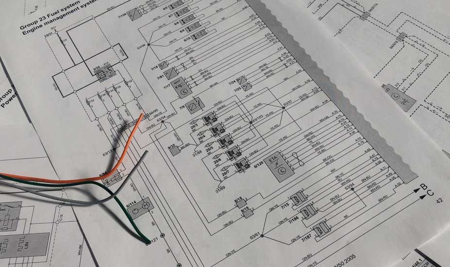
Wiring diagrams were traditionally printed in volume form, diagrams are big equally you know, to fit them all on one page would make them unreadable.
The solution – a number at the end of each circuit indicated the page on which the balance of the excursion diagram was continued.
This tin exist a little cumbersome, especially when referencing lots of dissimilar circuits at once.
Other solutions include showing just one system's wiring circuit to a page, for example, just showing the wiring diagram for the headlights. This works pretty well and was carried over to the digital age.
Digital wiring diagrams are a lot more efficient and easier to use, so if possible, always opt for digital schematics.
At present you know what the legend is and accept a cursory understanding of what the diverse symbols hateful, it's time to read a wiring diagram.
Near all modernistic diagrams are laid out with the power at the peak of the folio/screen and the ground at the lesser. This is the natural period, and it's the best way to read them.
The diagram below is a basic machine light excursion, at first sight, it might look complicated, but as you sympathize the flow, it will go clear.
Retrieve, battery power (voltage) at the acme of the page is trying to get to the ground at the lesser of the diagram.

Starting at the meridian of the included diagram, you can encounter power flows in two paths, (1) down to the low-cal relay (left) and (2) to the central electronic module (CEM) which is a control unit of measurement.
Diagram is fatigued with the ignition in position 0 – the "OFF" position.
Path (1) – The low-cal relay receives the voltage only, since the armature is in the open up/off position, it stops at this signal.
Path (ii) – The control module receives the voltage and that path ends.
The picture changes however when the ignition switch is in position two –"On".

The CEM module is programmed to offering a ground at X when the ignition is on. This as yous know magnetizes the relay whorl and causes the armature to close. The closed armature in turn offers a path for power to flow onwards to the switch.
The switch is now primed. Hit the light switch now allows voltage to flow through the light switch relay coil and grounds through the CEM integrated ground path.
The light relay roll is every bit you know, now magnetized and then it pulls the armature of the relay closed assuasive ability flow from path 1 all the manner through to the basis at the bottom of the diagram, powering the lights as it does and then. The circuit is now consummate.
That'south it, y'all've read the diagram, some circuits will exist more than complex, but the more you do, the improve y'all'll become.
Yous may also similar these posts:
- Car fuse keeps blowing
- OBD won't connect to ECU
- How to check fuel pump fuse
To encounter all the tools I utilise, check out the Auto electrical repair tools page. For instant digital admission to auto wiring diagrams and workshop manuals, bank check out the Emanuel link below.
Shop Car Manuals.![]()
What's the difference betwixt a diagram and a schematic? A diagram is a detailed map of a system and a schematic is a more simplified representation.
Source: https://rustyautos.com/how-to-read-car-wiring-diagrams/
Post a Comment for "How Ro Read a Car Wiring Diagram"